VLF TransAtlantic Test
8971.1 Hz 01-02 June 2014
Received by Paul Nicholson, Todmorden, UK, 6194 KM
Update:
Click for: December 2014 VLF Tests
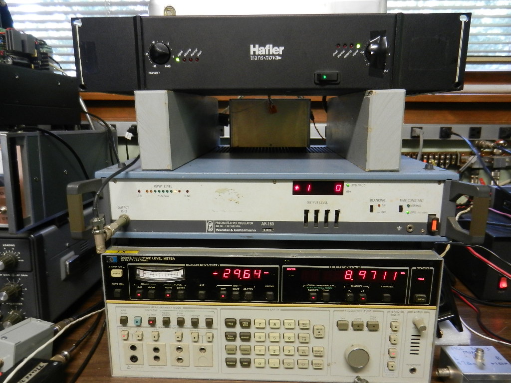
Signal Source and Amplifier
HP 3586B Selective Level Meter with tracking generator. Low level generator output is amplified by a WG A-160 level regulator. Output of level regulator feeds a Hafler P-3000 stereo audio amplifier bridge connected for mono output. This same generator and amplifier has been used on 137, 74 and 29 kHz.
Amplifier Cooling
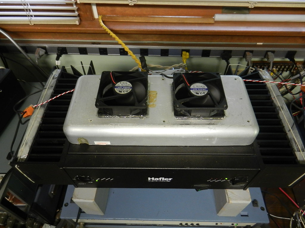
Three 12 volt DC fans provide on each heat sink provide lots of air for cooling. Two fans on top pull air through inside of amp. For this initial test the amp was producing very little heat I suspect because the output matching was far from optimum due to matching transformer.
GPS Frequency Reference
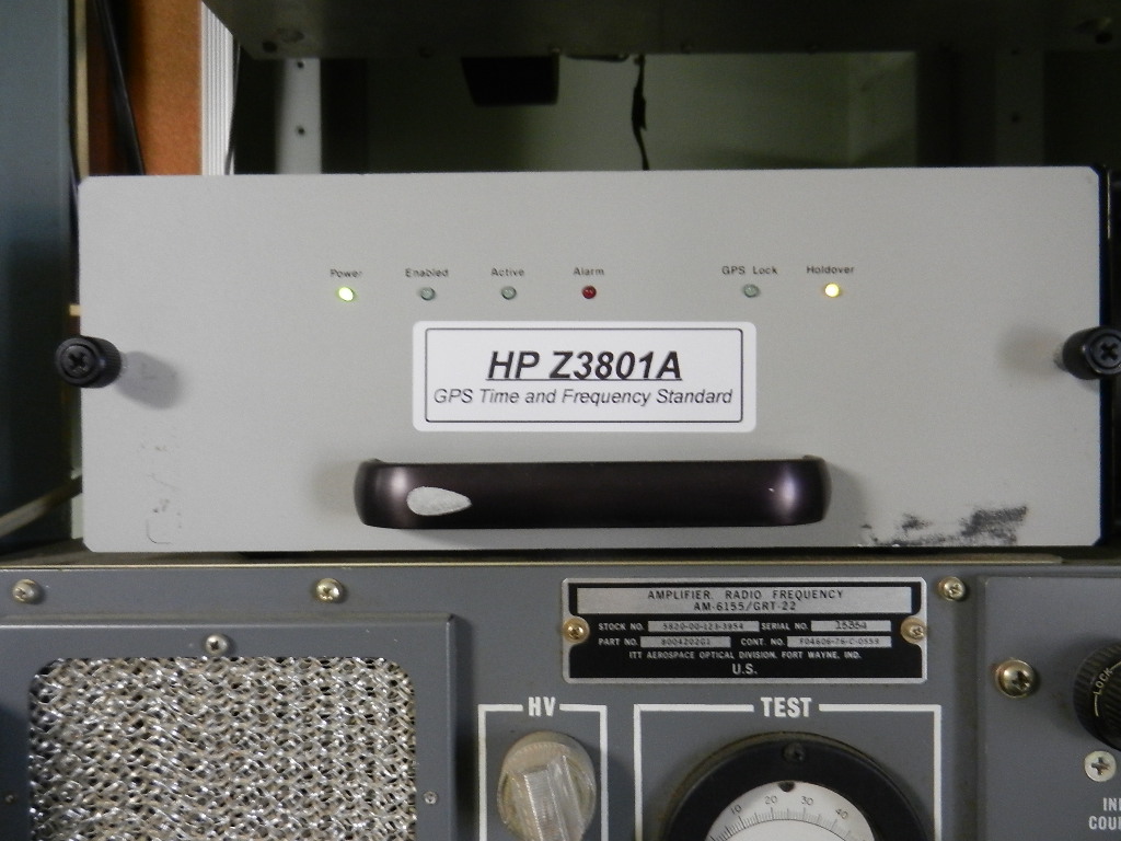
HP Z3801A time and frequency standard provides a 10 MHz reference signal to the HP 3586B SLM
Antenna
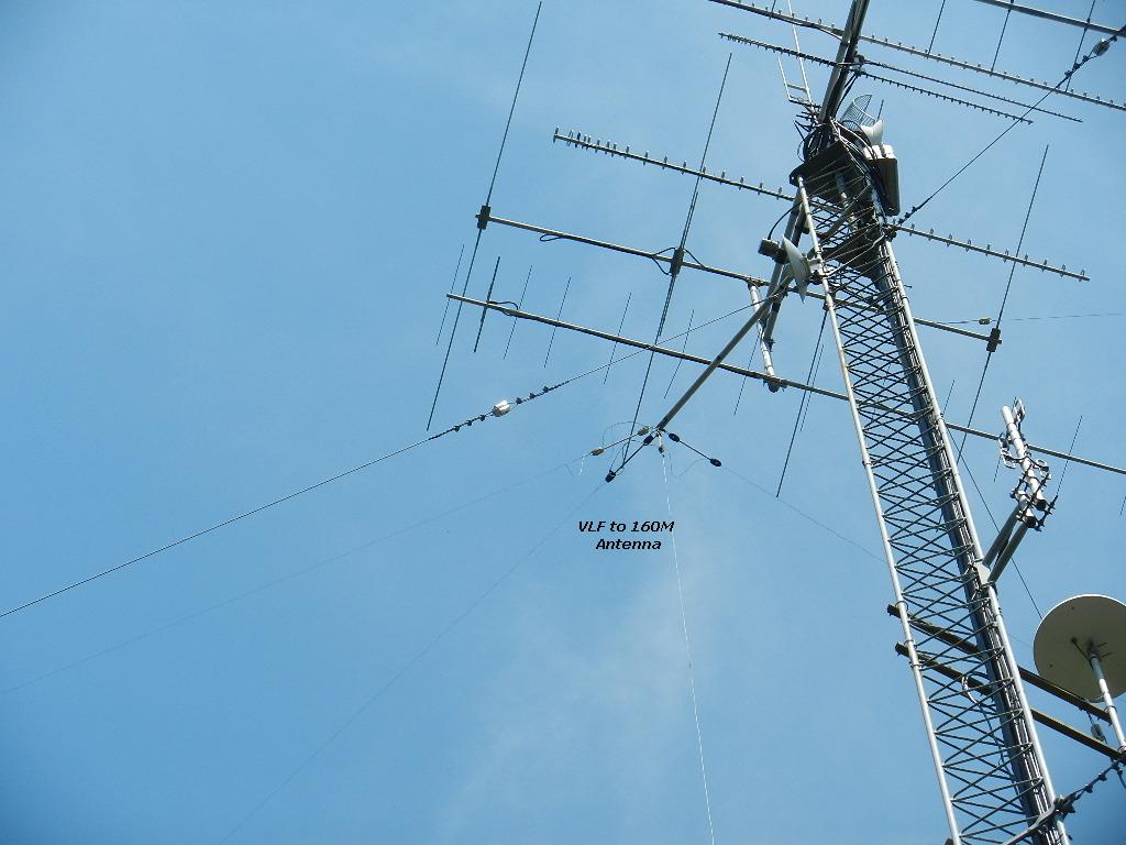
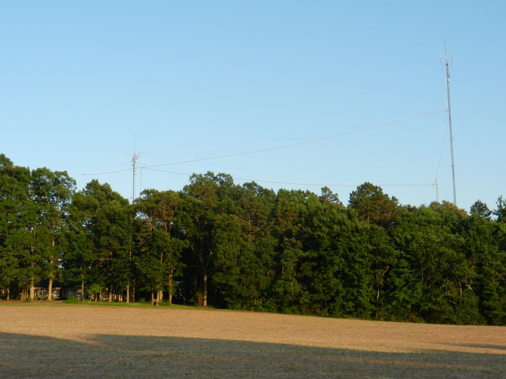
The same wire antenna that has been used for 1800, 500, 137, 74 and 29 kHz. The vertical wire is spaced 1.5 meter from the tower hanging from an insulator 29 meters above ground. Top hat consist of about 170 meters of No. 18 copperweld which has been up for over ten years and are now rusty. The top hat wires could not been seen in the original side view photo above so lines have been added to show location. Most of the top hat wires run about 7 to 20 meters over the top of a combination of oak and pine trees. Total antenna capacitance is close to 1200 picofarad.
Antenna Loading Coil
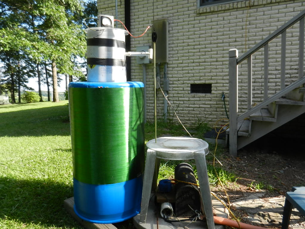
Antenna loading coil is 5030 feet of No. 22 enamel magnet wire wound on a plastic barrel which once contained silicon masonry sealer. Barrel diameter is 540 mm diameter by 840 mm length. Inductance measured about 265 mH. Without the bucket variometer on top the coil tunes the antenna to 9 kHz. Adding the ageing bucket variometer provides tuning down to about 8950 Hz.
Coil Winding
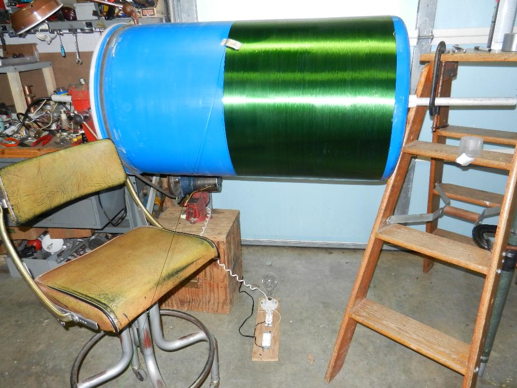
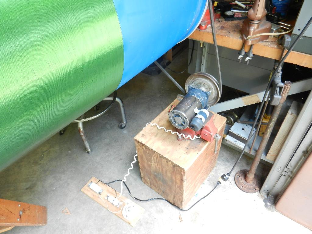
The gear motor turned the barrel at a comfortable winding speed with the pulley shown. Power to the motor was controlled by a foot operated rocker switch with an incandescent lamp in series. This was from another project so the lamp was not needed. The barrel just happen to have a nice groove near the top for the V belt. With proper tension on the belt, controlled by sliding the vice box, the barrel had enough torque to pull the wire from it's spool and give tight windings on the barrel. When a winding overlapped or when needing to stop the barrel was easily held in place by hand letting the V belt slip until the power was removed by the foot switch.
Impedance matching transformer
![]()
Initial test using the same matching transformer core used on 29 KHz produced very poor results. So I asked the rf experts who have helped me with many projects before, John, W1TAG and Jay, W1VD. They suggested I try either a 60 Hz isolation transformer or use a powerstat core.
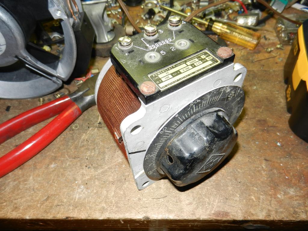
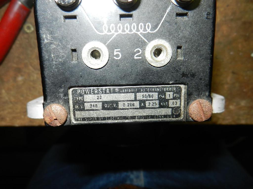
Core is from a small powerstat I found in junkyard. There was three identical powerstats in a rack mount panel which looked to be an old studio lighting control cabinet. One was operational after cleaning which I use to control the speed of a wood heater blower. The one disassembled for use as a matching transformer looks to have been overloaded, wiper burned and a section of the windings discolored but not shorted. I counted the original windings to be about 270 turns. The random length of wire I used for the primary winding made about 130 turns so I thought I would see what that would do before adding more turns. The way it is feeding the coil now is with the 130 turn winding connected to the audio amp and the original 270 turn winding feeding the antenna coil. I feel sure this isn't the optimum turns ratio or core material so I was surprised to see it to produce 1 amp antenna current.
Powerstat Before Disassembly
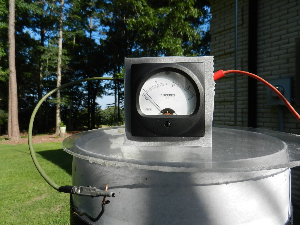
Antenna Current for Initial Transmission
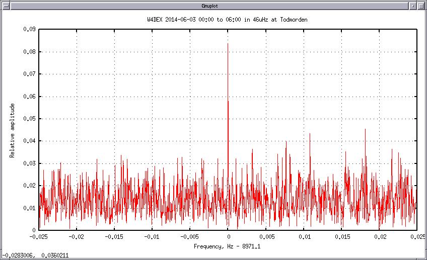
Signal spectrum as received by Paul Nicholson
Initial 8971 Hz reception
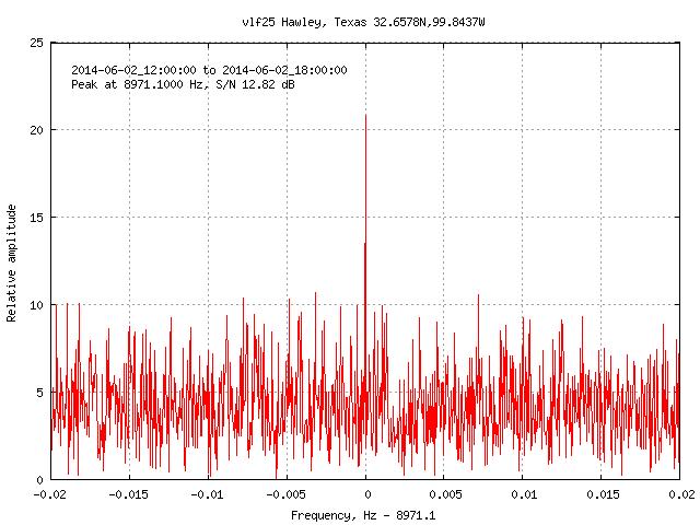
Confirmation reception on 8971.1 Hz
Received in Hawley, Texas
Reception Report by Paul Nicholson
At 2014-06-01 10:00 UT W4DEX began a long transmission of
GPS
locked carrier at 8971.000 Hz from 35.273N,80.371W.
Between 2014-06-02 00:00 and 06:00 a carrier was measured
at that frequency here in Todmorden 53.703N,2.072W with flux
density around 0.05fT. It was not very significant so I
combined the H-field and E-field receiver outputs (correcting
for their known phase and amplitude response) to produce a
uni-directional antenna response. This brought the signal up to
a significant level.
The signal bearing was roughly west. W4DEX is bearing 285 deg
from here. The S/N is max on a bearing of 315 degrees which
puts the prevailing south-westerly background nearer to the
side of the antenna response.
This gave the signal a respectable 12.5dB S/N in 46uHz bandwidth.
http://abelian.org/vlf/tmp/w4dex_140602a.gif
This was the strongest peak in a span of over 6500 Fourier
bins so is quite significant.
The carrier was also visible during the daylight path in 23uHz
bandwidth with average strength of around 0.02fT and with
similar S/N thanks to the lower day time noise and reduced
bandwidth.
At 2014-06-02 12:00 Dex altered the TX frequency for a blind
confirmation test. Six hours later the carrier (in 46uHz)
had vanished and a new signal appeared at 8971.100 Hz with
the same strength.
An email response from Dex confirms 8971.1 as the new frequency.
Range W4DEX to Todmorden UK is 6194 km.
Ratio of day/night flux density agrees well with LWPC
predictions for this path. LWPC predicts strongest night
signal between 00:30 and 04:30 and a sliding spectrum window
agrees with this.
LWPC requires ERP of 150uW to reproduce the observed flux
density. This is in the center of the ERP range estimated
from W4DEX antenna dimensions and measured antenna current.
--
Paul Nicholson
--
A partial list of those who made this happen:
Paul Nicholson who was convinced this could be done with so little radiated power and for his continuous prodding to give it a try
Paul's amazing weak signal software: http://abelian.org/vlfrx-tools/
Jay, W1VD and John, W1TAG - technical advice
Markus, DF6NM - technical advice and additional prodding
Mal, G3KEV for saying it can't be done and for the term "Dreamers Band"
Stefan, DK7FC - proving dreams can come true: www.qrz.com/db/DK7FC
Warren, K2ORS for the opportunity to experiment on 29 and 74 kHz
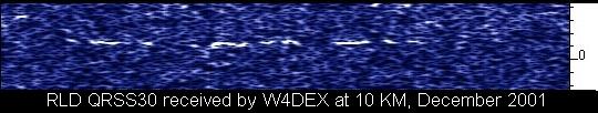
Brian, KD4RLD for his 2001 8.8 kHz transmission: kd4rld_8.8khz_dec2001.jpg
And all the other VLF experimenters who posted their results on the RSGB LF Group and the Yahoo Sub 9khz group
https://groups.yahoo.com/neo/groups/sub9khz/info